


Views: 0 Author: Site Editor Publish Time: 2026-08-31 Origin: Site


In extruded polystyrene (XPS) production, a single millimeter makes a massive difference. Manufacturing facilities face a harsh operational reality every single day. Thickness deviation during board production directly impacts material scrap rates, raw material costs, and product certification compliance. These dimensional deviations specifically threaten crucial R-value thermal ratings required by modern building codes. Achieving uniform thickness poses a highly complex core challenge. You cannot control this parameter through a single machine component. Instead, it requires a delicate balance of melt temperature, pressure consistency, precise foaming agent dispersion, and rigid downstream calibration. This article provides plant managers and procurement engineers with a highly practical framework. We will explore how high-quality extrusion systems manage these interconnected variables. You will learn to evaluate machinery designed to achieve and maintain strict thickness tolerances flawlessly across long continuous production runs.
Melt Stability is Prerequisite: A high-quality tandem XPS extruder is essential for delivering consistent melt pressure and temperature to the die head.
Die and Agent Synchronization: Uniform expansion relies on precise die-lip adjustments and consistent dosing of blowing agents (including eco-friendly CO2 systems).
Downstream Calibration: Continuous vacuum calibration and synchronized haul-off speeds are critical for locking in thickness before the board fully cools.
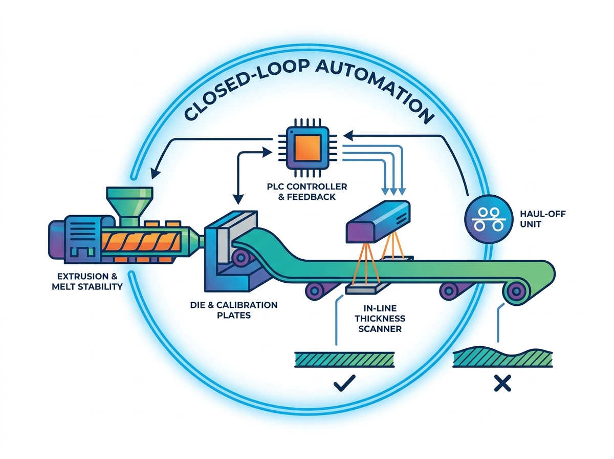
Closed-Loop Automation: Modern production lines utilize in-line thickness scanning with automated feedback loops to correct micro-deviations in real time.
Evaluation Focus: Buyers should prioritize demonstrable Factory Acceptance Testing (FAT) for thickness tolerances rather than theoretical maximum throughputs.
Precision matters intensely during the equipment decision stage. Before evaluating mechanical features, managers must understand the financial drain caused by unstable extrusion. Inconsistent board thickness creates a cascade of costly problems across the entire factory floor.
First, consider the phenomenon of material giveaway. Manufacturers often run machines "heavy" to ensure every board meets minimum gauge requirements. If your target thickness is 50mm, but your machine fluctuates by 2mm, you might set your baseline to 51mm. This intentional over-thickness silently destroys profit margins over high-volume runs. You end up giving away expensive polymer resin and blowing agents for free.
Uneven thickness also triggers severe compliance and quality standard violations. Modern building codes, such as those referencing ASTM C578 standards, demand predictable thermal resistance. Variations create air gaps when contractors install the boards. These gaps compromise thermal guarantees. Inspectors will reject entire batches if they discover inconsistent gauge metrics during spot checks.
Finally, dimensional instability causes downstream processing bottlenecks. Thickness variations wreak havoc on edge-profiling stations. When boards pass through cutting saws or routers for shiplap and tongue-and-groove profiles, they must sit perfectly flat. Variations cause machine jamming. They also lead to uneven cuts, producing unsellable scrap right at the final step of production.
Profit Erosion: Over-extruding by just 2% consumes thousands of dollars in excess raw materials monthly.
Installation Failures: Wavy boards prevent flush wall mounting, leading to contractor complaints.
Scrap Generation: Jammed edge-profiling equipment destroys nearly finished goods.
Uniform thickness begins long before the polymer reaches the die. It requires a flawless melt process. A modern tandem XPS extruder provides the mechanical foundation necessary to stabilize this process. The system architecture divides the labor between two specialized stages.
Primary Twin-Screw Extruder: This section handles aggressive melting and mixing. It ensures the polystyrene resin, nucleating agents, and flame retardants blend uniformly. It also introduces the blowing agent under high shear.
Secondary Single-Screw Extruder: This section focuses purely on cooling the melt and building consistent pressure. It reduces the polymer temperature to the exact point required for optimal foaming.
This division of labor isolates variables perfectly. A constant melt pressure before the die is absolutely non-negotiable for uniform foaming. If the pressure surges or drops, the foaming agent expands erratically upon exiting the die. Fluctuations here guarantee thickness surging in the final product. Physics dictates that pressure drops cause premature cell rupture, collapsing the foam structure locally.
When evaluating XPS foam extrusion equipment, you must heavily scrutinize the drive and gearbox components. Robust, low-pulsation gearboxes are vital. Inferior gearboxes create microscopic speed variations in the screw rotation. These variations translate directly into pressure pulses. A high-torque, precision-engineered gearbox ensures the polymer flows at an unwavering rate. This mechanical stability forms the bedrock of thickness control.
Best Practice: Always request vibration analysis data for the secondary extruder gearbox. High vibration indicates potential pulsation issues that will ruin board tolerances.
Once the melt leaves the secondary extruder, it enters the flat die. The mechanical design of this extrusion die dictates the initial geometric shape of the foam. Precision machining here is critical. The die must manage thermal expansion flawlessly across its entire width. Even a fraction of a degree in temperature variance across the die lip alters the polymer flow rate, causing thick or thin bands.
Operators rely on micro-adjustable die lips to fine-tune the profile. Traditional systems use manual push-pull bolts. Modern systems utilize automated thermal bolts. These bolts expand or contract based on electrical currents, allowing operators to execute micron-level adjustments safely while the machine runs.
Blowing agent variables severely impact this stage. Your choice of blowing agent dramatically alters melt viscosity.
Blowing Agent Viscosity Impact Comparison
Blowing Agent Type | Melt Viscosity Impact | Operating Pressure Requirement | Thickness Control Challenge |
|---|---|---|---|
CO2 (Carbon Dioxide) | Significantly lowers viscosity | Very High (250-350 bar) | Requires rapid cooling to prevent cell collapse. |
Ethanol / DME | Moderately lowers viscosity | Medium (150-200 bar) | Flammability risks require strict temperature limits. |
HFCs (Phasing Out) | Maintains stable viscosity | Low to Medium | Easier mechanical control, but environmentally restricted. |
Transitioning to environmentally friendly CO2 foaming introduces severe implementation risks. CO2 requires much higher pressure thresholds to remain soluble in the polymer melt. The equipment must handle this intense pressure without internal drops. Sudden pressure drops cause uneven cell growth. The cells grow too fast on one side, leading to severe board warping and wildly inconsistent thickness profiles. Upgraded die designs specifically engineered for CO2 dynamics mitigate this risk.
The moment the polymer exits the die, it expands rapidly. Without immediate physical constraint, it would form an unpredictable, round mass. This is where downstream calibration takes over. Adjustable upper and lower vacuum calibration plates sit immediately outside the die exit.
These plates strictly confine the physical thickness as the foam expands. They act as a rigid mold. The vacuum pulls the expanding foam against the chilled metal surfaces. This creates a smooth outer skin while forcing the internal cells to grow uniformly between the set gap. If these plates lack rigidity, the expanding foam will simply push them apart, creating over-thick boards.
Controlled cooling mechanics play an equally vital role here. You must extract heat from the board at a highly specific rate. If you cool the board too quickly, the outer skin hardens while the core remains molten. The core will eventually cool and shrink, causing the center of the board to sag. This center-sagging creates a concave thickness profile.
Furthermore, haul-off synchronization demands absolute precision. The haul-off caterpillar pulls the board through the calibration plates. The relationship between extruder output speed and haul-off speed must remain perfectly locked. Even slight motor desynchronization causes disaster. If the haul-off pulls too fast, it stretches the board, making it too thin. If it pulls too slowly, the material bunches up, creating thick ripples. High-end servo motors ensure this synchronization never wavers.
Relying on manual caliper measurements is no longer viable for high-volume production. Modern operations require automated closed-loop thickness measurement systems. These systems scan the board continuously as it travels down the line.
Manufacturers typically evaluate two primary in-line monitoring technologies. Ultrasonic scanners bounce sound waves off the board surface to calculate distance. Laser scanners use optics to triangulate the exact surface height. Laser systems generally offer higher accuracy, especially on textured surfaces. The scanner traverses back and forth across the entire board width, generating a real-time 3D topographical map of the product.
In-Line Scanner Technology Comparison
Technology Feature | Laser Scanning System | Ultrasonic Scanning System |
|---|---|---|
Measurement Accuracy | ±0.05 mm | ±0.15 mm |
Surface Sensitivity | Unaffected by density variations. | Can be affected by surface density changes. |
Environmental Resilience | Requires clean lenses; sensitive to heavy dust. | Highly resilient to dust and factory debris. |
Advanced PLC control systems use this scanner data to execute automated feedback loops. If the scanner detects a thick spot on the left edge, the PLC instantly sends a signal to the corresponding thermal bolt on the die. The bolt heats up, constricting the lip gap slightly to correct the micro-deviation. Alternatively, if the entire board runs marginally thick, the PLC can automatically increase the haul-off speed by a fraction of a percent to stretch it back into tolerance.
However, we must apply a trust and reliability lens here. I warn buyers against over-reliance on automation. Software cannot fully fix severe mechanical pressure pulsations. If your primary extruder surges violently, the closed-loop system will constantly chase the error, overcorrecting and making the problem worse. Automation only optimizes a mechanically stable baseline.
Upgrading your machinery requires a disciplined evaluation process. You cannot base decisions solely on theoretical maximum throughput numbers found in sales brochures. Instead, you need a buyer's checklist focused heavily on mechanical tolerances.
Inspect the secondary extruder gearbox for anti-pulsation features.
Verify the synchronization protocols between the extruder drive and haul-off motors.
Assess the metallurgical quality and thermal control zones of the flat die.
Confirm the rigidity and cooling capacity of the vacuum calibration plates.
You must also address implementation realities, specifically maintenance and reliability. Consider how easy it is to clean the die and maintain the calibration plates. Over time, polymer degrades and builds up on these surfaces. This buildup causes drag. Drag alters the flow rate and immediately impacts thickness. A well-designed machine allows operators to clean these critical components quickly without dismantling half the production line.
Common Mistake: Ignoring daily cleaning protocols for calibration plates will ruin thickness tolerances within a week, regardless of how advanced your machine is.
Finally, demand absolute proof of performance. You should require prolonged test runs during Factory Acceptance Testing (FAT). Do not accept a simple 10-minute sample run. Short runs hide pressure surging issues. Insist on running your specific resin and blowing agent formulations for several continuous hours. Use this time to verify continuous thickness consistency across hundreds of boards before you sign off on the equipment delivery.
Maintaining strict thickness tolerances requires a comprehensive mechanical strategy. Uniform board thickness is never an accident; it is the systemic result of synchronized primary extrusion, precise die design, and rigid downstream calibration. Any weak link in this chain guarantees dimensional failure and wasted materials.
To improve your operational efficiency, take immediate action. Audit your current scrap rates caused specifically by thickness deviation. Calculate the volume of resin you give away by running boards overly thick to pass inspections. Use that hard financial data to calculate the exact ROI of upgrading to precision-engineered equipment. Upgrading your extrusion technology will quickly transform those material losses into measurable profit margins.
A: Industry-standard acceptable deviation typically ranges from ±1mm to ±2mm. This depends heavily on the overall board thickness and the operational line speed. Thinner boards generally demand tighter tolerances. Achieving a continuous ±1mm tolerance requires highly stable melt pressure and automated closed-loop die control.
A: Line speed determines the available cooling time within the calibration plates. Pushing a machine past its rated cooling capacity means the board exits with a molten core. This leads to post-extrusion core expansion and uneven, wavy surfaces. High throughput must always match the system's cooling infrastructure.
A: Yes, significantly. CO2 requires much higher operational pressures to remain soluble. It also demands specialized mixing elements in the primary extruder. Failing to maintain this high pressure causes premature foaming and inconsistent cell structures, which directly result in severe surface and thickness variations.
A: Maintenance must be frequent. Operators should perform daily visual inspections of the calibration plates to remove polymer buildup. Buildup causes surface drag. Furthermore, technicians should recalibrate the in-line laser or ultrasonic thickness sensors weekly to ensure automated feedback loops receive accurate data.


